Back to: filters
configuration
Figure 1 shows a passive low-pass filter. A passive low-pass filter can be made by connecting a resistor and capacitor in series. The input is applied across these two components and the output across the capacitor. This type of filter is known as first-order. This is because there is only one reactive component – the capacitor.

how it works
Since capacitive reactance varies inversely with frequency, at low frequencies the capacitive reactance will be large, compared to the resistance of the resistor. This means that the voltage drop across the capacitor will be larger than the voltage drop across the resistor.
voltage divider
An RC low-pass filter is actually a voltage divider! Understanding this will help you to understand how it works. Rather than a voltage divider being constructed from two resistors, this one is comprised of a resistor and a capacitor. As with a two resistor voltage divider, there is a voltage drop across each component (Kirchhoff’s voltage law). However, with a change of frequency the voltage drop across each resistor remains constant but capacitors exhibit reactance, which varies with frequency! Therefore, you need to think of an RC low-pass filter as a voltage divider that has a voltage drop across the capacitor that varies with frequency, due to the change in reactance.
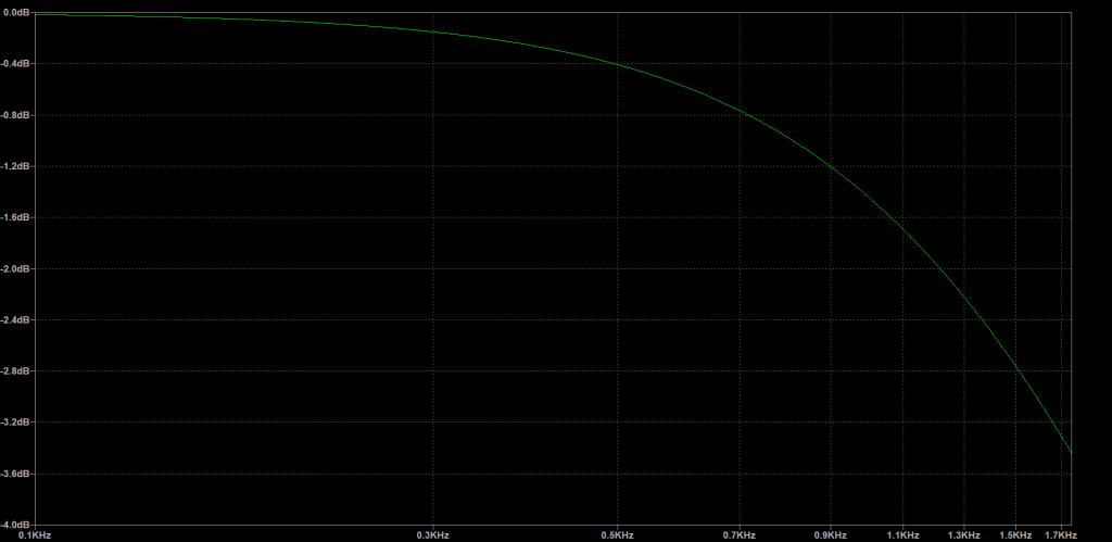
cutoff frequency
When designing a low-pass filter we need to decide on a point that the frequency should drop off, so we can only pass through the desired frequencies. Figure 2 shows what this looks like. There is a sharp drop off, which is known as a brick wall (because of its shape). However, the reality is that we cannot build a filter with such a perfect drop off! The reality is that the drop off will be more of a slope, see figure 3. Figure 3 shows a typical response curve of a real filter. When designing a filter, we use what is known as the cutoff frequency. The cutoff frequency is defined as the frequency above which the output voltage falls below 70.7% of the input voltage. This 70.7% is derived from the fact that this is the point that the capacitive reactance equals the resistance. We can calculate the cutoff frequency by using the formula: 1/2πRC. This is also when the power is 50% and there is 3dB of attenuation. At this point, the output is 3dB lower than the input! Note that some people say that the 3dB point is chosen as this is the amount of change that the human ear can distinguish a change – however, this has been disproven!
examples
Figure 4 shows three low-pass filters, with different values of R and C. I have calculated the cutoff frequency for each one, so you can see the effect that changing the resistance and capacitance has on the cutoff frequency

This works because the voltage on a capacitor cannot instantaneously change. when you have a resistor slowing the charging of a capacitor, the output voltage cannot follow the input voltage. As a result, higher frequencies get filtered out.
This means that at frequencies below the cutoff frequency, the signal passes through, unchanged. When we reach the cutoff frequency, we start to notice a reduction – it’s the point where we notice the filter having an effect.
The two sines waves no longer line up, there has been a shift in phase. The filter is adding a delay to the signal. Specifically, a negative phase shift – the output lags the input.
Describe filter characteristics with a graph called a bode plot.
ideal vs real
An ideal low-pass filter would remove all frequencies that are above the cutoff frequency, while allowing the rest to pass – unchanged.
However, the reality is that an ideal low-pass filter is impossible!